Common Gate Amplifiers
Contents
Common Gate Amplifiers#
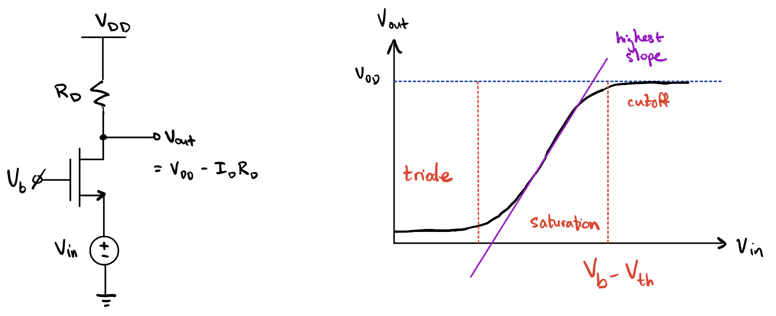
Fig. 45 Large-signal behavior.#
Where the slope is the highest is where you want to bias for max gain (given you have a large enough margin away from triode).
The conditions for saturation are as follows:
\(V_{\text{DS}} > V_{\text{GS}} - V_{\text{th}}\)
\(V_D > V_G - V_{\text{th}}\)
\(V_{\text{out}} > V_B - V_{\text{th}}\)
Small-signal gain#
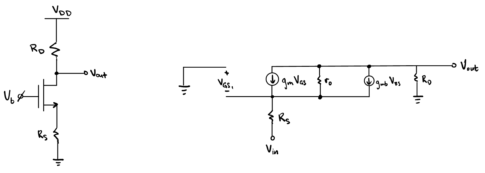
Fig. 46 Small-signal gain.#
The gain is given by
Input resistance#
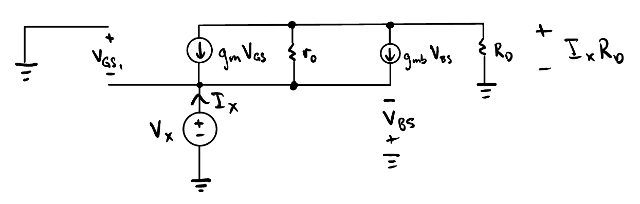
Fig. 47 Input impedance test voltage and current.#
Therefore,
The approximation above can be made if we assume \(g_m + g_{mb} r_o \gg 1\).
This has low input resistance. The output resistance is the same as for the common source with degeneration:
Summary
This is the only topology you can design input impedance to be a specific value.
✅ Good for impedance matching.
✅ Good as a current buffer/amplifier (current input).