Cascode Amplifiers
Contents
Cascode Amplifiers#
Cascode amplifiers are where MOSFETs are stacked on top of each other.
Cascode Amplifiers#
Large-signal behavior#
We know that \(A = -G_m R_{\text{out}}\).
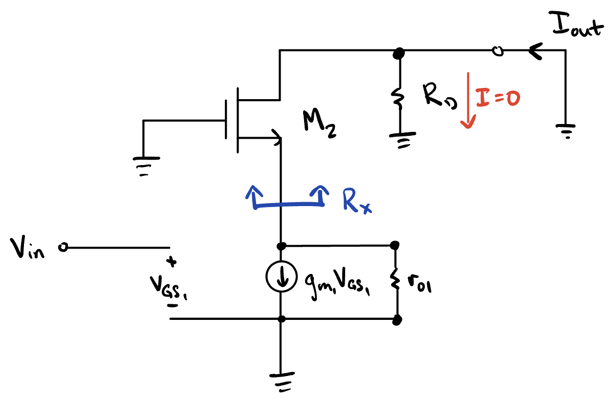
Fig. 48 Small-signal gain.#
which we know from the common gate topology. Knowing that, \(I_x\) can be reduced to
and
Impedance#
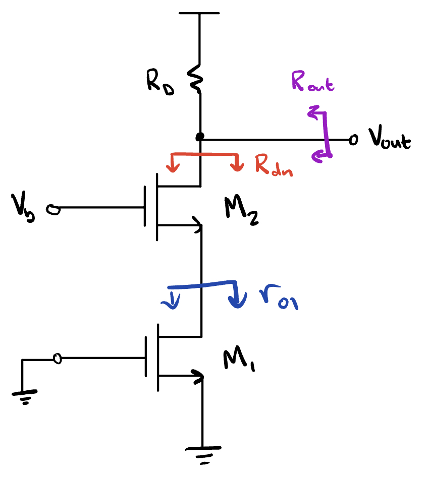
Fig. 49 Equivalent impedances.#
The output resistance is therefore
Small-signal gain#
The gain is given by
If \(R_D\) is made large, the cascode can have greater gain than some other amplifiers. If \(R_D = \infty\), then
The typical cascode implementation is shown below.
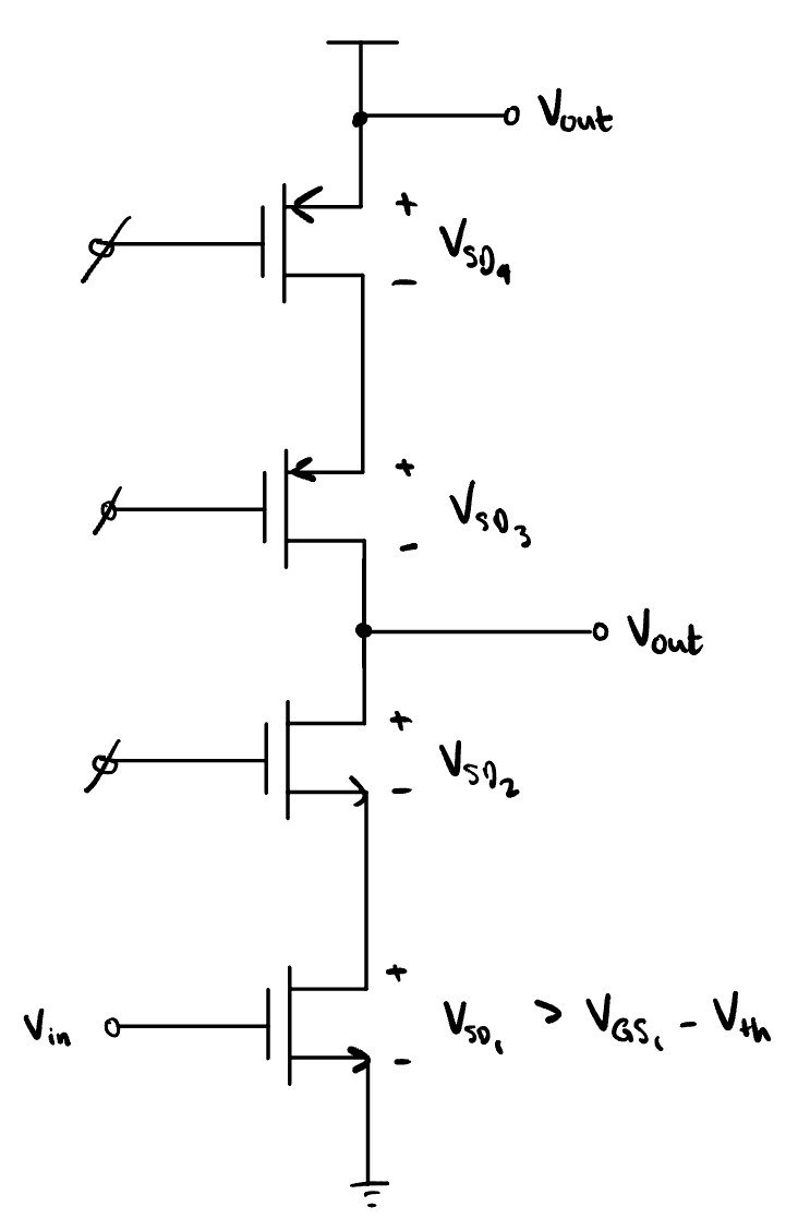
Fig. 50 Typical cascode implementation.#
With a cascode, the output swing is limited. All MOSFETs must be in saturation, and the max output swing is
or, what’s left over after all MOSFETs are biased to saturation.
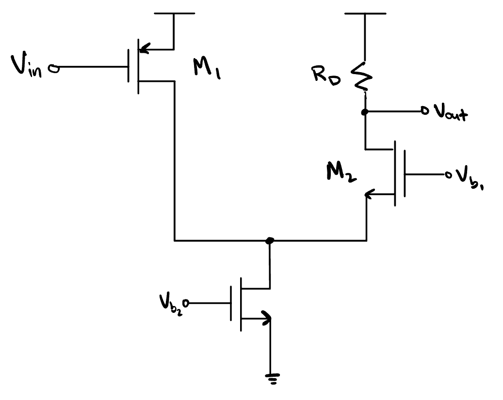
Folded Cascode#
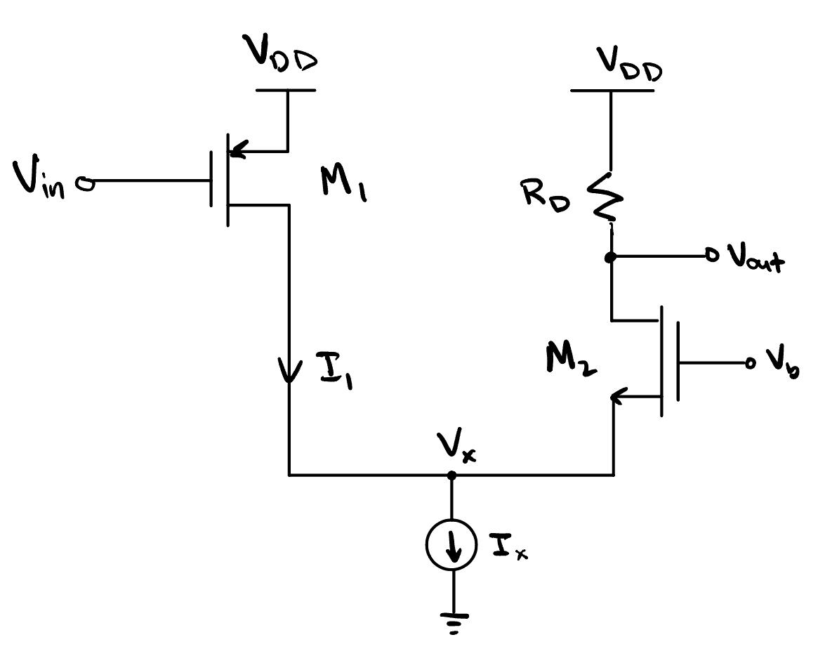
Fig. 51 Folded cascode circuit diagram. Note the MOSFET on the left is a PMOS, while on the right is an NMOS.#
Large-signal behavior#
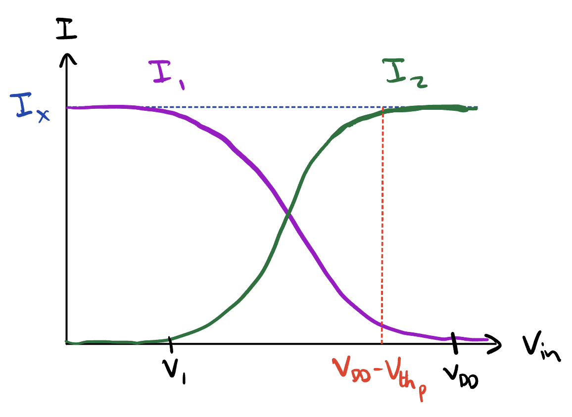
Fig. 52 Large-signal behavior.#

Fig. 53 Output voltage relative to input voltage.#
Small-signal gain#
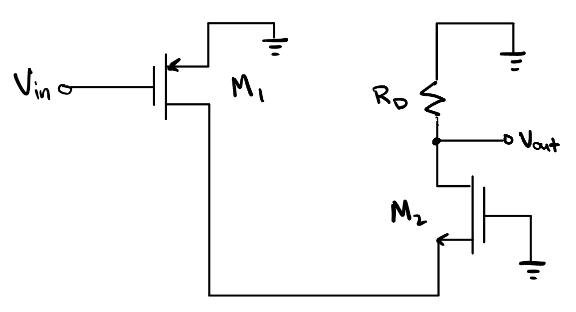
Fig. 54 Small-signal gain.#
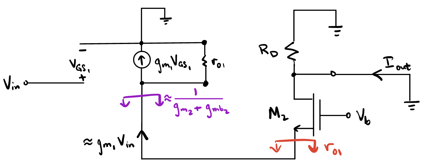
Fig. 55 Small-signal circuit model. Note the similarities it shares with the cascode model.#
And the gain is