Airport Operations#
Signs, markings & lightning#
Six types of signs installed at airports
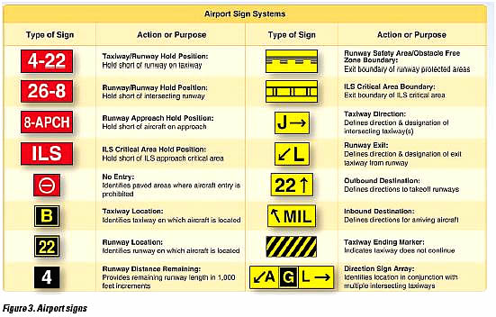
Fig. 1 Six types of signs installed at airports.#
Mandatory instruction signs: red background, white text. Denotes an entrance to a runway, critical area, or prohibited area.
Location sign: black background, yellow text, yellow border. Identifies taxiways, runway locations, boundary of a runway, ILS critical areas.
Direction sign: yellow background, black text. Identifies designation of intersecting taxiways leading out of an intersection.
Destination sign: yellow background, black text. Might contain arrows, provides directions to runways, terminals, cargo areas, civil aviation areas, FBO’s, etc.
Information sign: yellow background, black text. Provides pilots with information on areas that can’t be seen by the tower, radio frequencies, noise abatement procedures, etc.
Runway distance remaining sign: black background, white text. Shows remaining runway distance in thousands of feet.
Runway/taxiway marking colors
Runway markings are white. Edge lighting is also white.
Taxiway markings are yellow. Taxiway edge lighting is blue. Taxiway centerline marking is gren.
Chart supplement & airport/taxi diagrams#
The chart supplement contains data on public and joint use airports, seaplane bases, heliports, VFR airport sketches, NAVAIDs, communications data, weather data, airspace, special notices, and operational procedures. Current published versions can be found on the FAA’s website.
NOTAMs#
NOTice to Air Missions are notices filed with an aviation authority to alert aircraft pilots of potential hazards along a flight route or at a location that could affect the flight.
They can be looked up through an FAA website.
Runway incursion & collision avoidance#
Runway incursion
Any occurrence at an aerodrome involving the incorrect presence of an aircraft, vehicle or person on the protected area of a surface designated for the landing and take off of aircraft.
Wake turbulence avoidance#
Arrival
Note where a heavy aircraft touches down, and touch down after that point. Remain above the larger aircraft’s path while descending.
Departure
Note where the large aircraft rotated, and rotate before that point. Remain above and upwind of the leading aircraft’s path.
En route
Remain above and upwind of the larger aircraft’s path. Wake tends to descend about 500-900 feet behind the larger aircraft at distances up to 5 miles behind. Vortices descend approximately 300-500 fpm for the first 30 seconds.
SRM & CRM in the airport environment#
Crew resource management (CRM) and single-pilot resource management (SRM) is defined as the art and science of managing all the resources (both on-board the aircraft and from outside sources) available to a (potentially single) pilot (prior to and during flight) to ensure the successful outcome of the flight.
RM includes the concepts of
aeronautical decision making (ADM),
risk management (RM),
task management ™,
automation management (AM),
controlled flight into terrain (CFIT) awareness,
and situational awareness (SA).
SRM training helps the pilot maintain situational awareness by managing the automation and associated aircraft control and navigation tasks.
Towered & non-towered airport ops#
Towered
Contact tower for all instructions and clearances, including taxi, pattern instructions, etc. Get the ATIS before contacting the tower so you can advise them you have the weather.
Non-towered
Assume left hand traffic patterns, unless otherwise stated in the charts supplement, sectional, or landing indicator (around a wind tetrahedral). Enter on a downwind at a 45, intersecting approximately midfield. Traffic patterns are usually 1000 feet above the surface. Announce intentions on the radio.
Traffic pattern entry & exit, wind indicators#
Use left traffic patterns at 1,000 feet above the airport unless indicated otherwise.
Depart straight out or with a 45 degree turn in the direction of the traffic pattern’s crosswind leg.
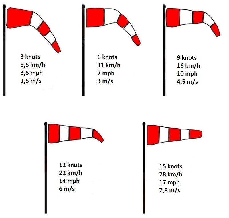
Wind indicators include wind socks, wind cones, and the tetrahedron.
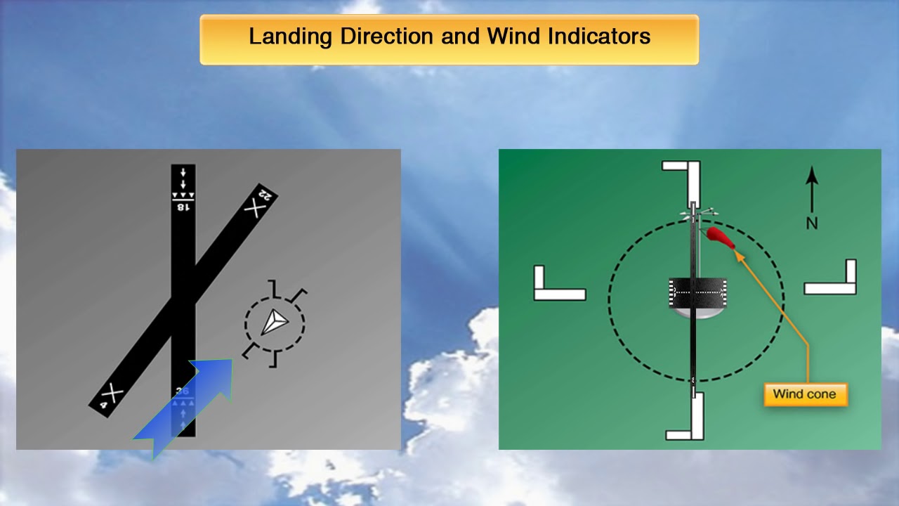
Fig. 2 Wind indicators and traffic pattern direction indicators. (source)#
Communication procedures#
4 W’s of ATC
Who you’re calling: Clearly state the name of the facility you’re calling
Who you are: State your full aircraft identification as filed in the flight plan
Where you are: State your position
What you want: State your request
Class B#
You must be explicitly cleared into Bravo airspace.
Class C#
Class C service requires pilots to establish two‐way radio communications before entering Class C airspace. If the controller responds to a radio call with, “(a/c call sign) standby,” radio communications have been established and the pilot can enter Class C airspace.
Class D#
Two-way communication must be established before entering Delta airspace. Acknowledgment of callsign is equivalent to the establishing of two-way communications.
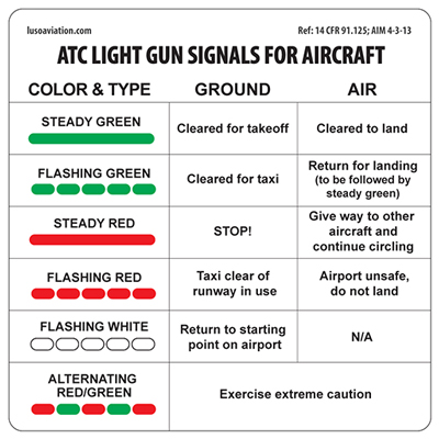
Lost communication & ATC light signals#
If you have a radio malfunction (transmit, receive, or both) and need to land at a towered airport:
Remain outside or above Class D until direction or flow of traffic is determined.
Advise tower of aircraft type, position, altitude, and intention to land (if you have transmit).
Continue, enter pattern, report position as appropriate, watch for light signals from tower (see diagram below).
If transmitter becomes inoperative, follow above procedures and monitor appropriate ATC frequency.
Acknowledge by rocking the wings (daylight) or blinking the landing light (night).